Improvement of AP-/DP- and manoeuvring performance
by rudder force measurement
System advantages:
- Reliable and safe dynamic positioning/manoeuvring operations
- Less rudder motion in DP and AP mode
- Energy savings through improved efficiency
- Elimination of aft tunnel thrusters on a case-by-case basis
- Emission reduction
- “Quieter” rudder system
- Reduced manoeuvring response times
- Significantly less rudder motion
- Reduced waste and maintenance costs
Computerised manoeuvring operations today
Modern dynamic positioning systems (DP) and auto-pilot systems (AP) utilise a variety of input signals to maintain course or position, e.g. from positioning reference sensors, combined with wind sensors, motion sensors, gyro compasses, GPS data, etc. These data are processed by an IT system to allow the course or drift to be predicted and to calculate countermeasures controlling the actuators in the vessel’s propulsion system. Input data and processing is of high quality, but only reflects the vessel’s motion response. Inertia causes a massive decrease in the strength of these control signal, which do not meet or provide sufficient quality for manoeuvring. For rudder-propeller arrangements relatively high corrections were applied to rudder angle, resulting in the generation of high rudder forces. The vessel turns more than necessary for the predicted course correction, resulting in a similar counter-action in the opposite direction. This effect results in hysteresis, or rudder flipping, causing the steering gear to work continuously and more or less strong fluctuations around a set course or position.
Consequences
Modern computerised navigation and positioning systems use rather general output signals to operate the rudder controls for manoeuvring. This is why the rudder force generated for specific rudder angles is not available to the system. Predictions of the reaction forces from specific rudder angles fall short due to various disruptive factors such as wind, speed, drift in a vast number of possible combinations that cannot be determined in advance. This means, for example, that the rudder of a 100,000 dwt tanker travelling at a speed of 14 knots under AP navigation moves continuously in a +/- 5 degree range, resulting in a significant increase in fuel consumption. A similar situation occurs with operation in DP mode, but at much greater rudder angles, resulting in even greater fuel consumption and intensive unsteady operation of prime mover and steering gears. Especially the operation mode on twin screw vessels shows potential for savings. In this case, one propeller continuously pulls astern.
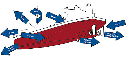
Influences and reaction forces on ship hull
Development Approach
The problems described above were urgently addressed to provide a solution to our costumers. To improve manoeuvrability under computerised DP + AP support systems there is a need for timely, direct or indirect measurement of rudder forces, which currently allows the generated lift and resistance to be determined. For this purpose, a force measuring arrangement or a method for measuring the rudder force should be developed which is able to determine rudder force vectors by direction and amount. By using current rudder force as input parameters for a DP or AP system, manoeuvring hysteresis can be eliminated or significantly reduced. In a first approach rudder force measurement arrangement will be applied on full spade rudders, because these rudders provide - in contrast to semi spade rudders - a mechanically explicit statically determined system. An installation on the rudder trunk and the rudder shaft is possible for the force measurement arrangement by sensors or strain gauges. The best feasible solution should be determined in the project. In difference to a state-of-the-art manoeuvring arrangement an interface has to be developed to calculate the appropriate rudder angle for a demanded manoeuvring force as an input for the steering gear. It also will process the measured forces, adjust the rudder angle and provide feedback to the DP system about the actual forces.
To meet the requirements of this system Becker developed a force measurement arrangement for full spade rudders, capable of determine rudder lift, drag and an interface for processing the sensor signal and transferring force data to the DP system. The interface provides standard protocol (NMEA 0183) as well as analogue signal output. The receiving system requires the capability of processing real time force signals, predicting force development on corresponding actuation from the current thrust-rudder force condition.
The improved performance in manoeuvrability will lead to more reliable and safer operation in DP, fewer manoeuvring motions with lower fuel consumption and reduced emission of CO2, NOX, SOX, etc. In addition, fuel consumption will be significantly reduced when one main engine on a twin screw vessel is being operated in standby mode. Using shaft generators as a PTI device might be conceivable as a back-up solution where full main engine power is not required for DP operation. Several prime mover manufacturers are thinking about using shaft generators for propulsion powered by auxiliary diesel. These arrangement capable of providing sufficient performance for DP manoeuvring with auxilliary power and all main engines on standby require further study.
Signal processing
In difference to a state-of-the-art manoeuvring arrangement an additional interface unit is required in the Becker Intelligent Monitoring System (BIMS®) to calculate the forces generated. The signal provided by a single sensor represents a value for the rudderstock bending on only one coordinate axis. This axis is dedicated to the rudder coordinate system, which is unfortunately turning with the rudder. The control unit will calculate each force component from four sensors signals and transform these into rudder coordinates for the appropriate components that can be used by the vessel’s coordinate system. Rudder force information is sent via the network and can be received by any navigation control system connected to it. To maintain the integrity of these systems the received data is used to refine the results from standard operation mode. Data validation is performed by defined allowable deviation from navigation system results as well as BIMS internally by considering all input values and checking for plausibility.
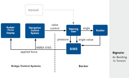
Function plan of rudder force measurement system
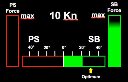
Rudder Force Display
BIMS® is able to display rudder forces at any place with network access. Three display modes are available:
- Display totals for lateral force and drag values (e.g. for adjustment, load determination, etc.). This mode can also be used to indicate that rudder force is low and only little response is expected under current conditions.
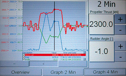
- Display a graph showing force application over time in chronological sequence. This mode makes it possible to visualize force maxima and to adjust the optimal rudder angle and RPM (propeller thrust). This ensures optimal rudder performance, especially in emergency situations.
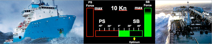
- Indicate the optimal rudder angle for a specific speed and rudder force actually applied in relation to maximum force.
Influences and reaction forces on ship hull
Rudder force display
Economic effects
Decreasing control operation of the amplitude and frequency of all components in the propulsion system along with increased manoeuvrability in AP mode results in fuel savings of approx. 2-3% with a corresponding reduction in emissions. For the DP mode, the expected savings will be significantly higher due the operation characteristic, but this can’t be accurately quantified, because of unsteady disturbances. In standby operation of one of two main engines savings of approx. 50% in fuel and emissions can be expected in DP mode. Considering that offshore vessels will in future be operating in ”Emission Controlled Areas“ (ECA), requiring the use of expensive desulphurized fuel, savings will increase even further. A subsequent reduction in wear on the bearings will also result in an extension of maintenance intervals from the current two years to an interval corresponding to the class required for 5-year dry-docking. This will increase overall vessel availability to such an extent that a short return on investment can be achieved.
|